Home/Blog/BTU Load Calculator: How to Size Every Zone, Pick the Right Equipment, and Feed Your Duct Design
BTU Load Calculator: How to Size Every Zone, Pick the Right Equipment, and Feed Your Duct Design
August 14, 2026
Dr. Rajesh Rolen
5 min read
A BTU load calculator helps HVAC contractors and engineers determine how much airflow and equipment capacity each zone actually requires under design conditions. This page focuses on zone-level BTU calculation, HVAC duct sizing, and the Manual J to Manual D workflow used to convert load data into buildable duct systems.
Oversized Equipment Costs More. Undersized Equipment Creates Complaints.
Zone-by-zone load calculations help HVAC Contractors choose the right equipment before installation. DuctArchitect's Heat Load Calculator turns those calculations into reports that support equipment selection and duct design.
No credit card required. Get 14 days of full access.
The content is written for professionals using a heating and cooling load calculator or AC BTU calculator to make accurate airflow, equipment sizing, and duct branch sizing decisions tied directly to real project conditions.
Key Takeaways
Zone-level BTU calculation determines the airflow and duct branch size required for each room or zone.
Whole-building estimates fail in HVAC duct sizing because airflow demand differs by zone.
BTU load data feeds directly into CFM calculation, equipment selection, and Manual D duct design.
The Manual J to Manual D workflow depends on accurate per-zone load inputs from the start.
Incorrect glazing, climate, and ventilation assumptions create duct sizing errors that remain after installation.
What a BTU Load Calculator Actually Outputs (and What It Does Not)
A BTU load calculator is only useful when its output connects directly to zone airflow and duct design decisions. For HVAC contractors and engineers, the real value is not the load figure itself. The value is how that figure drives CFM calculation, HVAC equipment sizing, and duct branch sizing across the project.
The output supports:
Identifying the minimum required equipment capacity for the zone
Calculating the CFM (cubic feet per minute of airflow) needed to deliver that capacity
Determining the duct dimensions required to carry that CFM to the zone
Establishing the basis for equipment selection under Manual S
The output does not decide:
Which specific equipment model to install (that requires checking manufacturer performance data at actual design conditions, not rated conditions)
What duct sizes to use (that requires the CFM calculation and Manual D)
Whether duct losses were accounted for (only if you entered duct routing data as an input)
Whether the calculation meets permit documentation standards (a certified Manual J calculation is required for permitted work, not a BTU calculator output)
Every contractor and engineer who uses an HVAC size calculator without understanding these boundaries will eventually produce a system that looks correctly sized on paper and performs incorrectly in the field. This distinction matters because HVAC duct sizing begins where the calculator output ends. The next step is understanding the difference between space load and system load before translating BTU data into airflow.
The Difference Between Space Load and System Load
Most BTU calculator content stops at the space load figure. HVAC system performance problems begin when contractors assume that number represents the total demand the equipment must actually deliver. Space load is the BTU/h figure produced from the room or zone inputs alone. System load includes duct losses, leakage, and ventilation impact. Space load and system load are not the same thing in HVAC design. Space load represents the thermal demand of the conditioned room or zone. System load represents the actual capacity the HVAC equipment must deliver after accounting for duct heat gain, duct leakage, and ventilation load. In systems with poor duct insulation or attic duct routing, the system load can exceed the space load by 25 to 30 percent.
System load equals space load divided by a system efficiency factor that reflects duct quality and routing conditions. A well-sealed duct system inside conditioned space stays close to 1.0 efficiency. Unsealed attic ductwork can reduce system efficiency to 0.70 or 0.75. If the BTU load calculator does not include duct loss inputs, the output should be treated as a space load estimate only. The distinction between these two figures becomes critical once airflow is distributed across multiple zones. That is where whole-building estimates begin to fail and where duct performance problems start to appear.
Cooling Load vs. Heating Load: Why Your Calculator Produces Two Different Numbers
A heating and cooling load calculator produces separate peak values for cooling and heating. Those figures will almost always differ. Here is how to apply each correctly.
Use the cooling BTU/h to select cooling equipment capacity and size cooling duct airflow
Use the heating BTU/h to select heating equipment capacity
Never average the two figures
Never apply the larger figure to both modes
For heat pump systems: verify the unit's rated heating capacity at the actual heating design temperature for the project location, not at standard rated conditions, as heat pump capacity decreases significantly at low outdoor temperatures
These rules prevent common HVAC equipment sizing mistakes that create short cycling, airflow imbalance, and comfort complaints. Correct interpretation of the calculator output matters as much as the calculation itself.
Whole-building BTU estimates are adequate for selecting total equipment capacity. They are not adequate for HVAC duct sizing. Duct systems are designed around airflow distribution per zone. Each zone carries a different load profile based on solar exposure, occupancy, equipment load, and duct routing conditions.
Zone-level BTU calculation matters because duct systems distribute airflow by branch, not by whole-building averages. High-load rooms such as west-facing offices, attic-exposed spaces, and conference rooms require different airflow volumes than interior low-load zones. When airflow is distributed evenly instead of by actual zone demand, the system delivers the correct total airflow while failing to maintain room-level comfort.
Rooms with the highest cooling demand frequently receive insufficient airflow because their branch ducts were sized from averaged building data instead of actual zone BTU requirements. This is not an installation issue. It is a calculation issue built into the duct design before installation even begins. The next step is defining zones correctly before running the first calculation.
How to Define Zones Before You Run a Single Calculation
Thermal zoning determines how airflow is distributed across the building. Incorrect zoning produces incorrect CFM allocation, even when the total system capacity appears correct. Each thermal zone should correspond to a shared load profile, thermostat condition, and controllable duct branch. Defining these boundaries correctly is what allows zone-level BTU calculation to support accurate HVAC duct sizing.
Orientation-based zoning
South-facing and west-facing spaces experience different solar gains than north-facing interior rooms. Combining them into one airflow zone produces compromised CFM distribution. These differences become more severe in buildings with large glazing areas. Separate zone calculations prevent undersized duct branches in high-solar-load rooms. Correct orientation zoning improves airflow balancing during peak afternoon conditions. It also reduces persistent comfort complaints in perimeter spaces.
Use-based zoning
Conference rooms, server rooms, private offices, and retail areas carry different occupancy and equipment loads. A server room with constant equipment heat should never share a load calculation with a lightly occupied office zone. Load diversity matters because occupancy patterns directly affect airflow demand. Separating these uses improves HVAC equipment sizing accuracy and duct branch performance.
Duct-branch-based zoning
Every independently balanced duct branch should correspond to a defined thermal zone in the BTU calculation. If the duct system cannot independently regulate airflow to separate spaces, the zoning strategy exists only on paper. This approach keeps airflow delivery aligned with the physical duct system. It also prevents overcomplicated zoning layouts that cannot be balanced in the field.
Floor-level zoning
Upper floors carry roof conduction load while lower floors may experience slab-related thermal losses. These load differences justify separate calculations in most multi-storey projects. Floor-by-floor zoning improves long-term temperature stability across the building. It also reduces airflow imbalance between upper and lower levels during seasonal peak loads. Correct zoning improves airflow balancing, register sizing, and long-term room comfort. Once the zones are established, the next step is converting zone BTU load into usable airflow values.
A Field-Ready Input Checklist for Running a BTU Load Calculation
The accuracy of an AC BTU calculator depends entirely on the quality of the project inputs. Missing or estimated inputs create inaccurate airflow calculations and incorrectly sized duct systems. HVAC contractors should collect these inputs before finalizing any equipment or duct sizing decisions.
Site measurements and building geometry inputs
Per zone:
Conditioned floor area
Ceiling height
Window dimensions and orientation
Window type and glazing performance
Exterior door area
External shading conditions
Per building:
Wall and roof insulation values
Floor assembly type
Air leakage condition
Existing equipment capacity for replacement projects
These measurements establish the thermal envelope used in zone-level BTU calculation. Incorrect geometry inputs produce inaccurate airflow demand throughout the HVAC system.
Climate and location inputs
ASHRAE design temperatures
Heating design temperature
Cooling dry-bulb temperature
Cooling wet-bulb temperature
Climate zone classification
Altitude correction requirements
ASHRAE design temperatures are especially important because airflow demand changes significantly under peak conditions. Using average climate values instead of design conditions produces incorrect HVAC equipment sizing.
Internal load inputs
Occupancy count and activity level
Lighting wattage
Computer and equipment loads
Server room heat output
Ventilation airflow requirements
Commercial ventilation load is frequently underestimated in field calculations. High-occupancy buildings often require significantly more airflow than envelope load alone would suggest.
This checklist creates the foundation for accurate CFM calculation and duct branch sizing. Once these inputs are verified, airflow calculations become far more reliable during Manual D design.
Converting Zone BTU/h Into the CFM That Feeds Your Duct Design
BTU load calculation is the starting point of HVAC duct sizing. The next calculation determines how much airflow each zone requires.
The required CFM depends on:
Zone BTU/h load
Supply air temperature
Indoor setpoint temperature
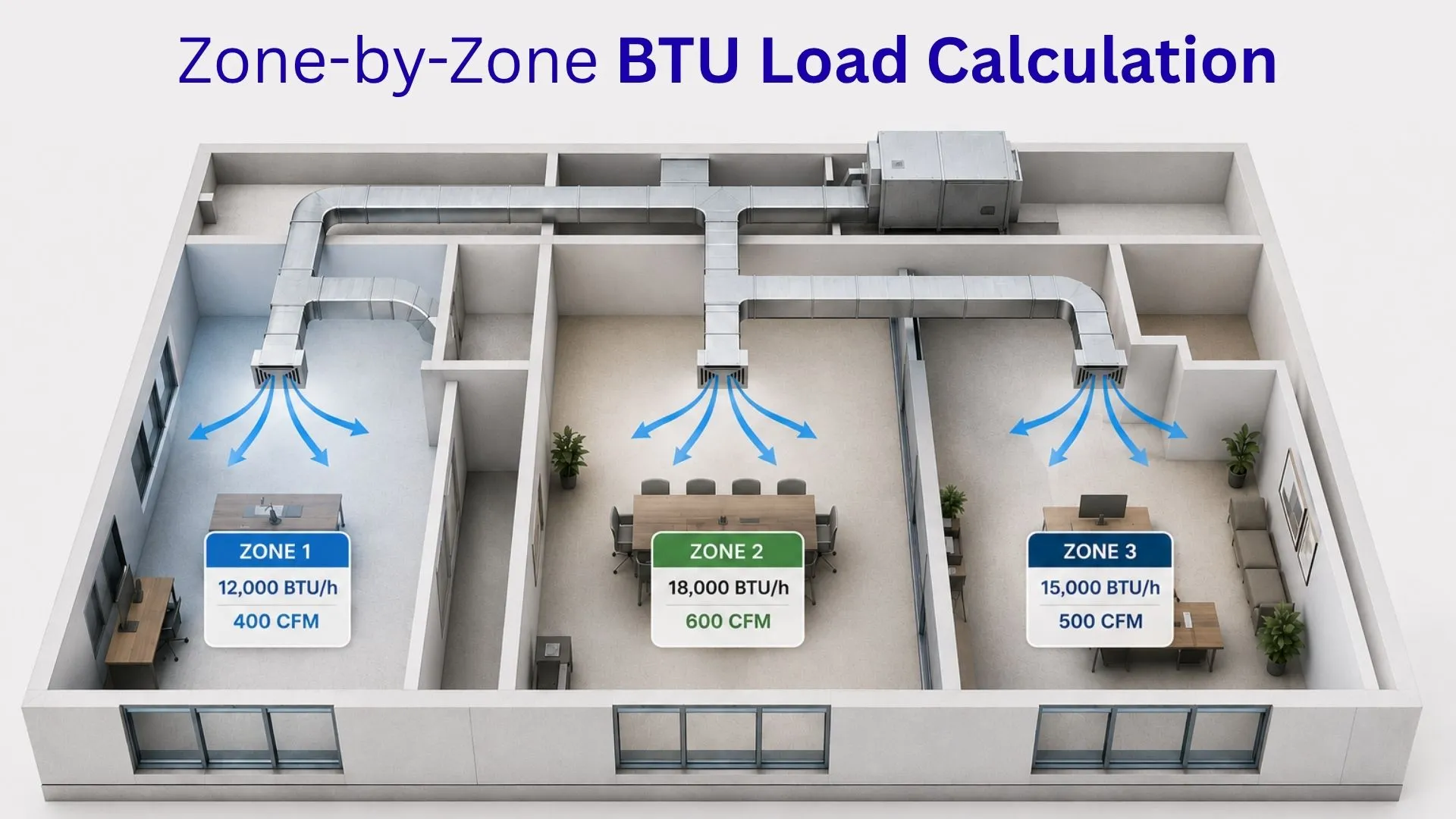
For standard cooling systems delivering 13 to 15°C supply air into a 24°C room, roughly 400 CFM is required per 12,000 BTU/h of cooling load.
What the zone CFM figure drives
The calculated airflow value determines how air moves through the duct system and how that airflow is delivered into occupied spaces.
Duct branch size serving the zone
Supply register size and quantity
Air velocity and static pressure balance
Total system airflow distribution
If total system airflow is distributed equally instead of by zone demand, the HVAC system will create uneven temperatures even when the installed capacity appears correct. Accurate airflow distribution is what separates a balanced HVAC system from one that constantly struggles with hot and cold rooms. Proper CFM allocation also improves Manual D duct sizing accuracy and system efficiency. For broader airflow strategy and digital system planning, see theHVAC system design trends. The airflow calculation becomes the bridge between BTU load and equipment selection. That is where sensible heat ratio and Manual S become important.
Sensible Heat Ratio and HVAC Equipment Sizing
Some BTU load calculators outputs separate sensible and total load values. The ratio between them is the sensible heat ratio, or SHR.
SHR affects how cooling equipment handles temperature reduction and moisture removal under real operating conditions. A standard residential split system typically operates at an SHR between 0.70 and 0.75. Low-SHR spaces such as gyms, restaurants, and humid commercial buildings require equipment capable of handling higher latent loads.
How to apply SHR in equipment selection
Correct SHR application requires matching the equipment performance profile to the actual zone conditions, not just the nominal BTU rating.
Match equipment SHR to the zone load profile
Verify manufacturer performance data at actual design conditions
Evaluate variable-speed systems in high-latent-load applications
A system that reaches setpoint temperature while leaving humidity unresolved has usually been selected without considering SHR performance. SHR becomes especially important in humid commercial environments where latent load dominates system behavior. Correct equipment selection improves comfort stability and prevents moisture-related complaints.
Correct equipment selection depends on more than nominal BTU rating. That is why the Manual J to Manual D workflow exists.
The Manual J to Manual D Workflow
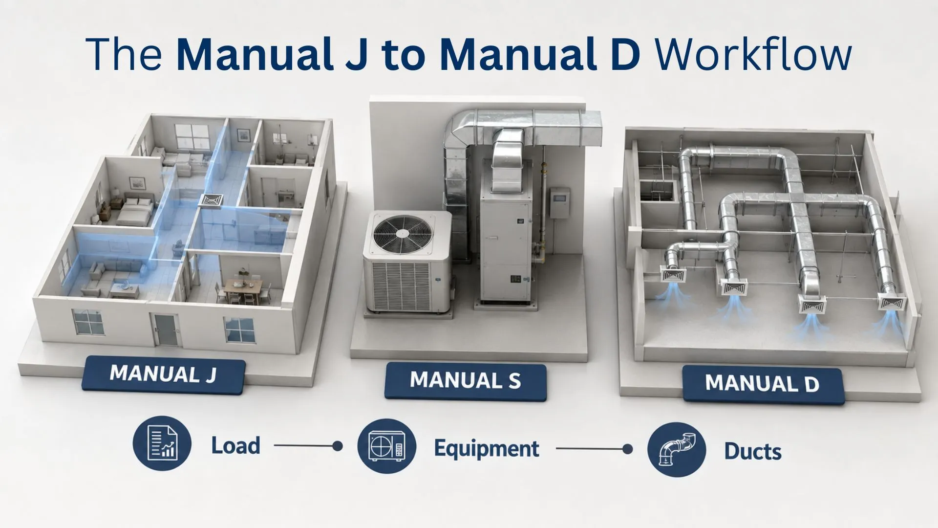
The Manual J to Manual D sequence connects load calculation, equipment selection, and HVAC duct sizing into one engineering workflow. Each step depends on the accuracy of the step before it. Incorrect inputs at the load stage create airflow and duct sizing errors that compound through the entire system design.
Manual J: The Load Calculation Standard
Manual J is the residential load calculation standard referenced in model building codes. For a full methodology breakdown, see theHVAC load calculation software guide. Use a BTU calculator for field estimates, scoping conversations with clients, and preliminary sizing checks. When the project will result in a permit application, a duct design deliverable, or a signed proposal with documented sizing, run or commission a full Manual J calculation.
Manual S: Using the BTU Output to Select Equipment Correctly
Manual S verifies whether the selected equipment can actually deliver the required capacity and airflow under project design conditions.
Contractors frequently select equipment from nominal tonnage alone. Manual S checks:
Actual cooling capacity at design conditions
SHR compatibility
Required airflow delivery
Static pressure limitations
Skipping Manual S often results in systems that appear correctly sized while underperforming in the field.
Manual D: How the BTU Load Becomes a Duct System
Manual D converts per-zone CFM requirements into duct dimensions, airflow balancing strategy, and friction rate limits.
The process determines:
Duct branch sizes
Supply and return duct dimensions
Velocity targets
Static pressure control
Every duct dimension begins with accurate zone BTU data. Incorrect load inputs produce incorrect airflow values, and incorrect airflow values produce incorrectly sized ductwork. For a broader breakdown of airflow distribution and HVAC hardware interaction, see the components guide.The Manual J to Manual D workflow exists because HVAC systems fail when airflow distribution is treated as an afterthought. Accurate airflow design starts with accurate zone-level load calculation and ends with properly balanced duct delivery.
BTU Reference Ranges by Space Type
Reference ranges help contractors establish a rough scoping estimate before running a full zone-level calculation. These values should never replace Manual J calculations or be used as the sole basis for HVAC duct sizing.
Residential Space BTU Ranges
Space Type
Size Range
Cooling BTU/h Range
Single bedroom
Up to 14 sq m
5,000 to 7,000
Large bedroom or master suite
14 to 28 sq m
7,000 to 12,000
Living room (enclosed)
20 to 35 sq m
8,000 to 14,000
Open-plan living and dining
35 to 60 sq m
14,000 to 22,000
Full-floor open plan (residential)
60 to 120 sq m
22,000 to 42,000
Light Commercial and Office Space BTU Ranges
Space Type
Size Range
Cooling BTU/h Range
Private office (1 to 2 occupants)
10 to 20 sq m
5,000 to 9,000
Open-plan office
40 to 100 sq m
18,000 to 48,000
Meeting room (6 to 8 people)
20 to 30 sq m
10,000 to 18,000
Small retail unit
40 to 120 sq m
18,000 to 55,000
Restaurant dining area
40 to 100 sq m
24,000 to 65,000
Server room or IT closet
Any size
Requires dedicated calculation
When the Reference Range Stops Being Useful
Reference ranges become unreliable in buildings with unusual geometry, extreme climate exposure, high-performance envelopes, or complex ventilation requirements. Any project involving HVAC duct sizing, commercial permitting, or multi-zone airflow balancing requires full zone-level BTU calculation instead of square-foot estimates alone.
Three BTU Calculator Input Errors That Produce Incorrect Duct Sizing
Most HVAC airflow problems are not installation failures. They originate in the input assumptions used during load calculation.
Error 1: Using Whole-Building Window Area Instead of Per-Zone Data
West-facing glazing carries significantly higher solar gain than north-facing glass. Averaging window area across the building underestimates airflow demand in high-load rooms.
The correction is to enter the glazing area and orientation independently for every zone.
Error 2: Using Incorrect ASHRAE Design Temperatures
Average climate temperatures are not the same as ASHRAE design temperatures. Using incorrect design conditions understates heating and cooling load, which reduces required CFM and under sizes duct branches.
The correction is to source design temperatures directly from ASHRAE climate references for the project location.
Error 3: Omitting Ventilation Load
Ventilation air must be conditioned before reaching occupied spaces. Omitting this load produces understated airflow demand and elevated system static pressure. Commercial spaces with high occupancy are especially vulnerable to this mistake. The correction is to calculate ventilation load separately and include it before equipment selection or duct branch sizing.
These three input errors compound through the entire HVAC workflow. Duct Architect’s workflow helps contractors connect accurate zone-level load calculations directly to airflow balancing and Manual D duct sizing decisions.
Conclusion
A BTU load calculator determines far more than equipment capacity. It determines the airflow each zone requires and the duct dimensions needed to deliver that airflow correctly. Zone-level BTU calculation improves HVAC duct sizing accuracy, airflow balancing, and long-term room comfort. Whole-building estimates cannot support branch-level airflow distribution in real projects.
Zone BTU/h → Zone CFM → Duct Branch Size → Room-Level Comfort
Every shortcut taken during load calculation compounds into equipment selection and duct design errors later in the workflow. Contractors who calculate per-zone airflow correctly build systems that perform correctly from the start.
FAQs
1. How accurate is an online BTU load calculator?
An online BTU load calculator is only as accurate as the project inputs entered into it, including zoning, glazing, insulation, airflow conditions, and ASHRAE design temperatures. For a deeper breakdown of methodology and permit-level documentation requirements, see the HVAC load calculation software guide Permitted projects and duct design work still require Manual J verification.
2. Why should I calculate BTU load per zone rather than for the whole building?
Zone-level BTU calculation is required because airflow demand differs between rooms based on glazing, occupancy, equipment load, and duct routing. Whole-building estimates create uneven airflow distribution and produce incorrectly sized duct branches in high-load areas.
3. How does a BTU load calculation connect to duct sizing?
BTU load determines the CFM required for each zone. That airflow value determines duct branch dimensions, register sizing, and system balancing requirements. The process follows the Manual J to Manual D workflow used in professional HVAC system design.
4. Can I size ductwork using only square footage?
No. Square footage does not account for window orientation, ceiling height, occupancy, equipment heat, or solar gain. Two rooms with identical floor area can require completely different airflow volumes and duct branch sizes.
5.Why does my HVAC system cool unevenly between rooms?
Uneven cooling usually means airflow is being distributed incorrectly across zones. High-load rooms often receive insufficient CFM because the original BTU calculation used averaged building assumptions instead of zone-level load data.
D
Dr. Rajesh Rolen
Published on August 14, 2026
Share:
Enjoyed this article?
Explore more insights and industry knowledge in our blog collection.